![]()
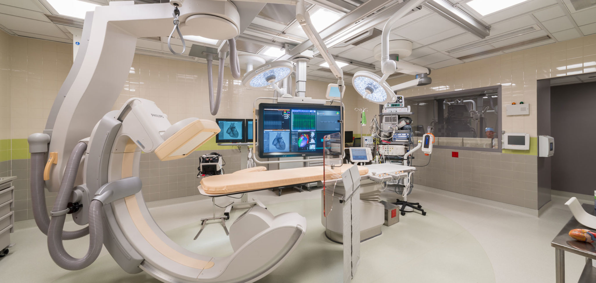
The most common diagnostic maneuver in the EP lab
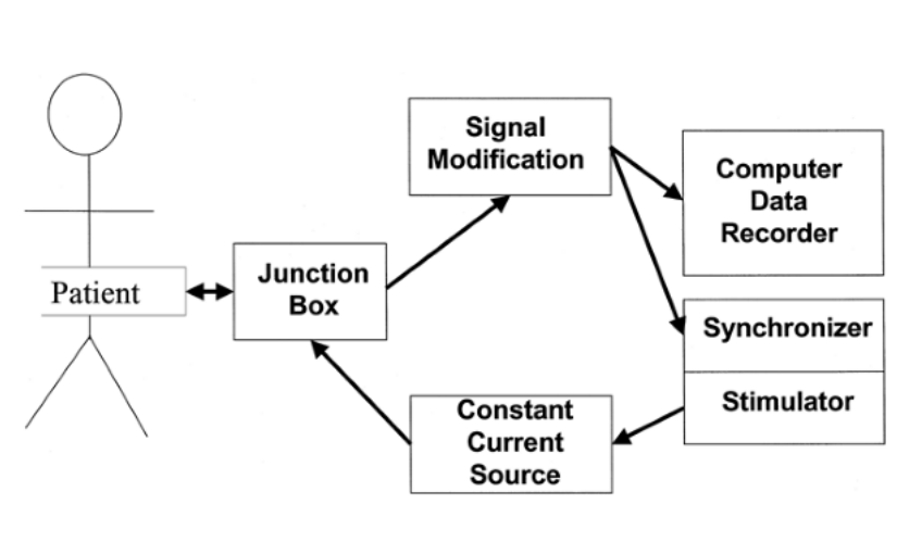
From the patient to the display
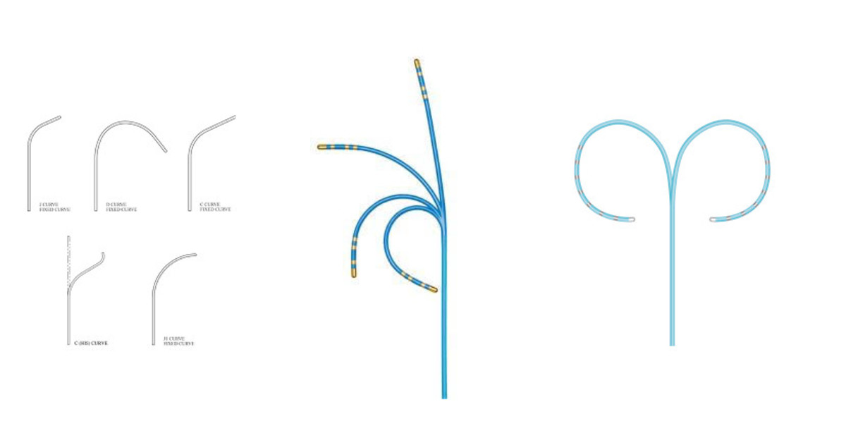
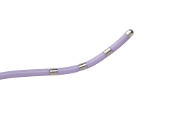
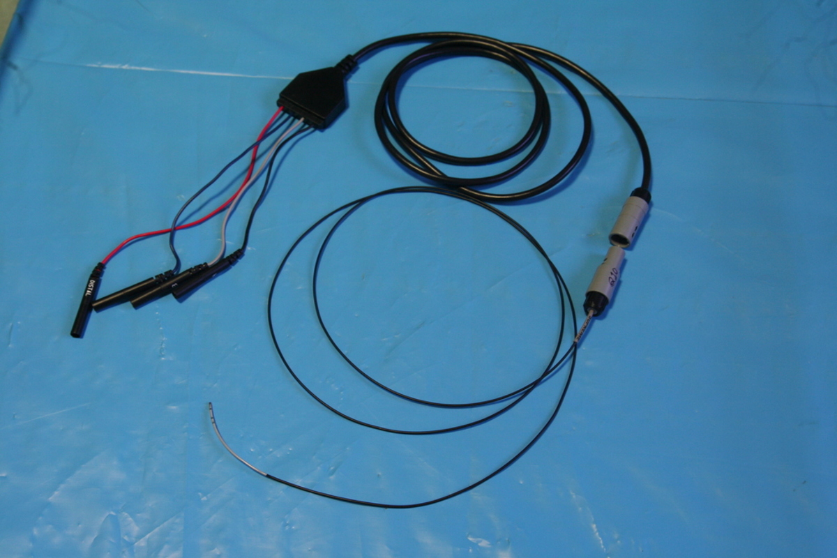
Catheters
Naming of electrodes
Connectors
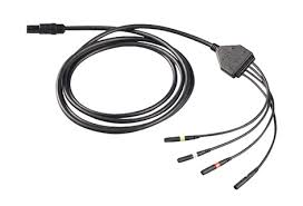
Connectors
Junction box
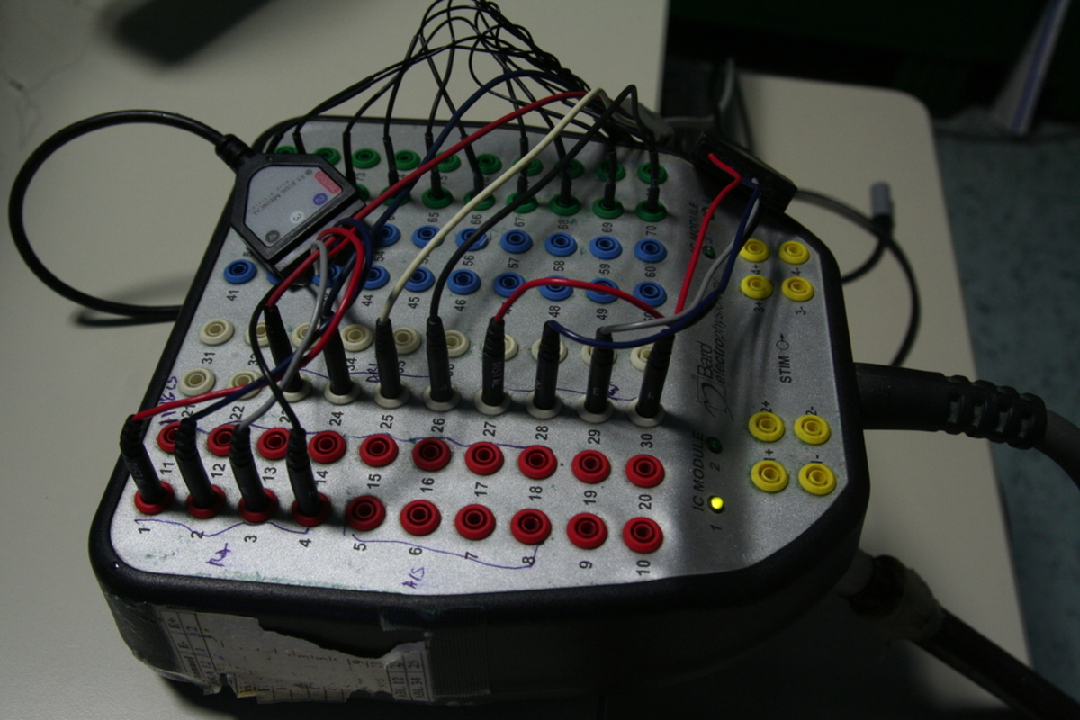
A bird's eye view
Signal and Noise
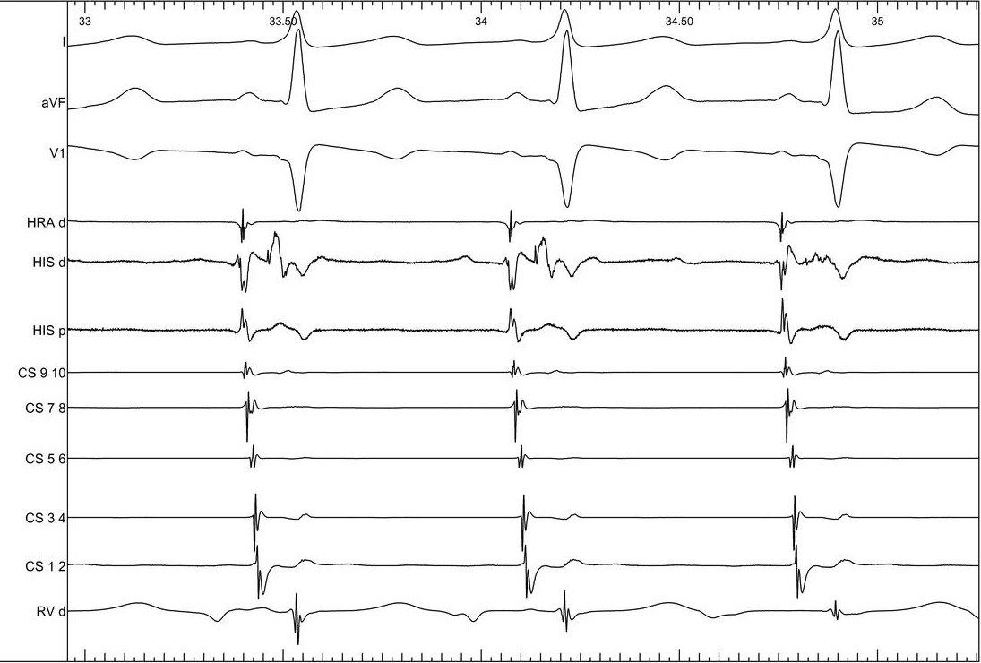
The challenge of intracardiac electrograms
- Very small amplitudes
- His bundle signal 0.5 mV
- Critical regions within scar may have smaller voltages - 0.25 mV
- Variation in signal amplitudes
- Surface ECG - 5 mV
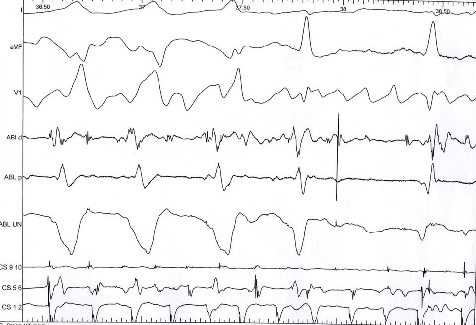
Noise
Noise
- Multiple sources of noise
- Patient as antenna - picks up signals from wiring and other devices
- Leakage current from devices connected to the patient
- RF energy - 70 V RMS
- Noise level in bandwidth of interest should be 10 times smaller to give SNR > 10
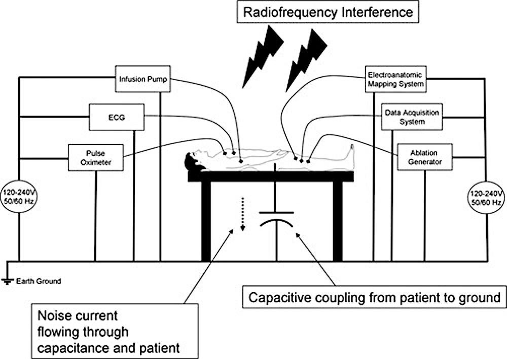
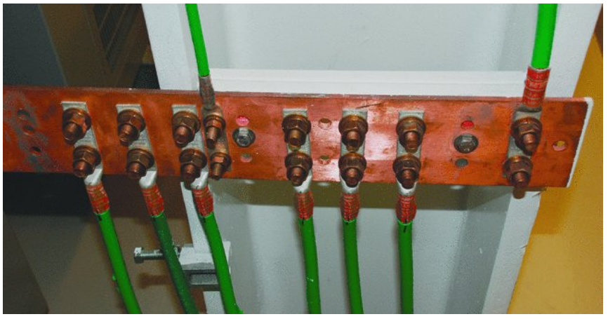
Earth Ground
- Physical connection from equipment to zero electrical potential of the earth
- Offers path for leakage current to flow
Principles to reduce noise / interference
- Decrease at source rather than reduce afterwards
- Radiation shielding also reduces electrical interference
- Separate all power cables from signal carrying cables
- When close, these should be perpendicular and not parallel
- Minimize coiling of cables
- Minimize distance between amplifier and source (patient table)
Differential amplifier
- Amplifies difference between two inputs
- Common signal is not amplified (Common mode rejection)
- Can be used to remove interference more effectively by tightly coiling two cables recording bipolar signal
- Inputs need to be balanced (ablation tip set for pacing)
Driven right leg
- Not required for recording 12 lead ECG
- Inverted noise signal sent for cancellation
- Good connection necessary to reduce noise
Practical tips to reduce noise
- Skin prep - dry abrasion
- Switch off unused equipment
- Try different sockets if persistent noise from an equipment
- Good grounding for all equipment
- Two return patches
- Amplifier close to patient
- Low pacing output - 2 mV, twice threshold
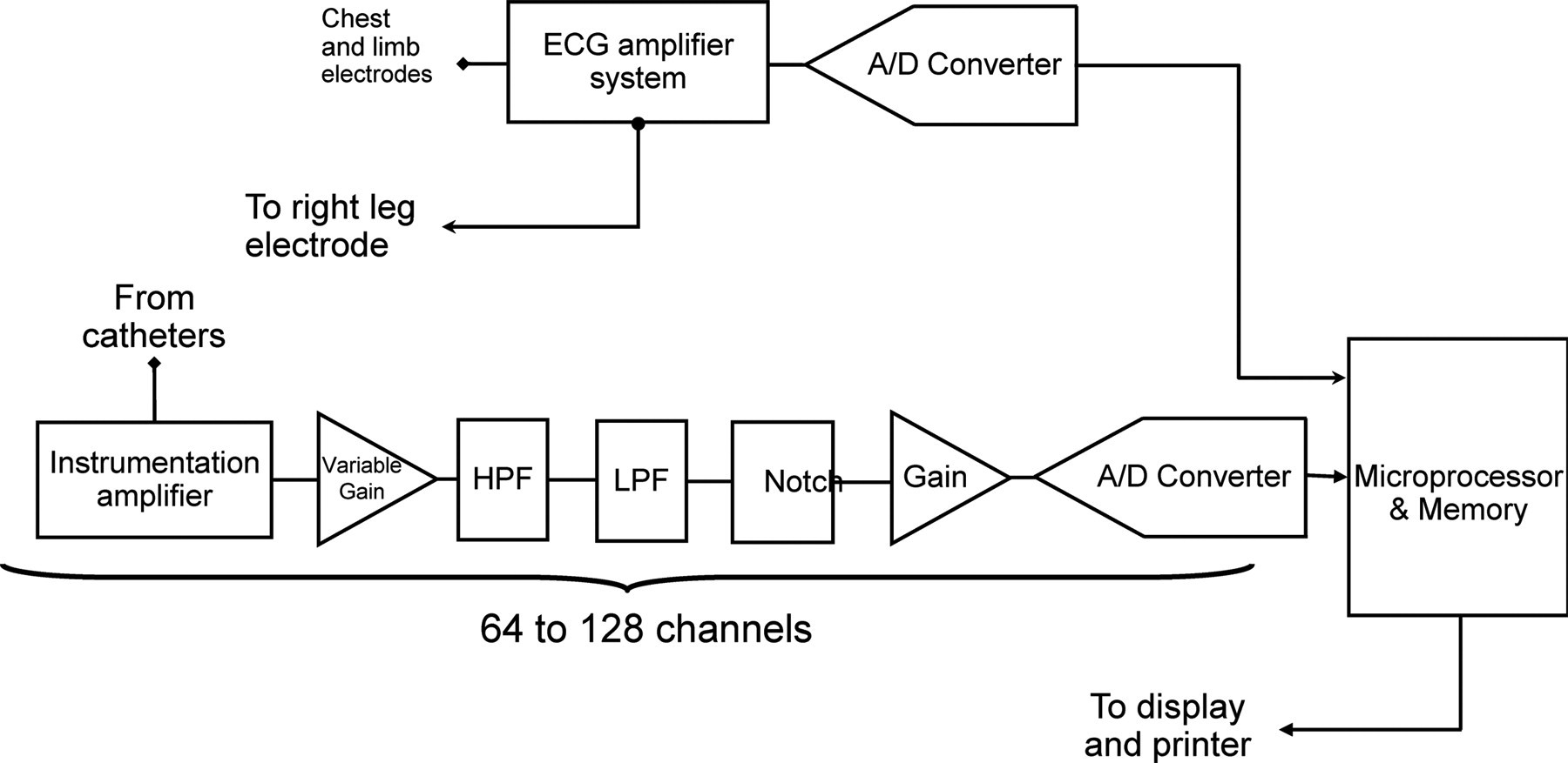
Signal processing
Steps
- Digitization
- Amplification
- Filters
- High pass
- Low pass
- Notch
Digitization
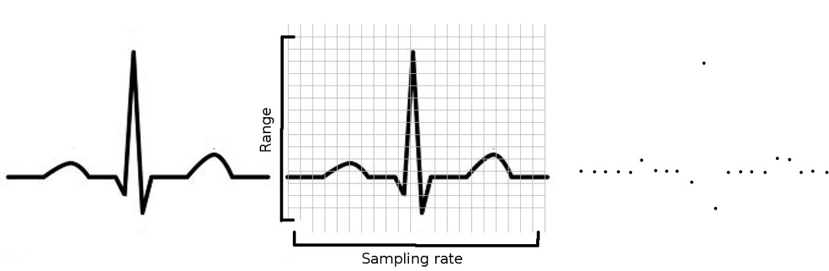
Resolution and sampling
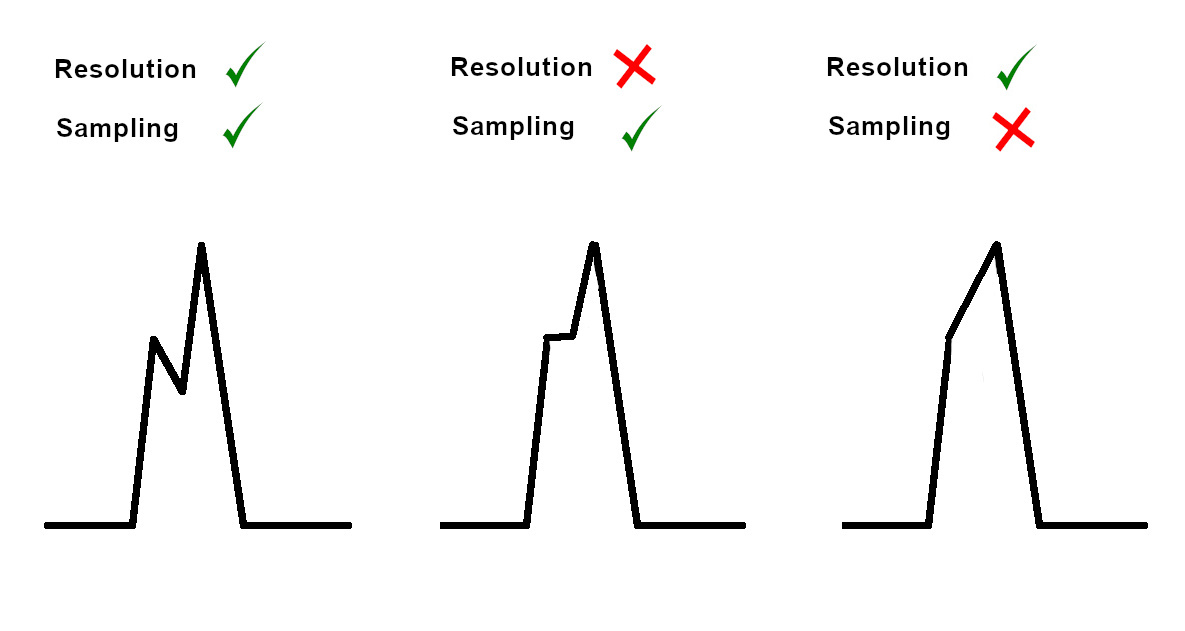
Nyquist limit
- Sampling rate should be at least twice the frequency of interest
- Lose high frequency information
- Aliasing
Filter Types
- Low pass
- High pass
- Band pass - achieved by cascading LPF and HPF
- Notch - can introduce noise also, can attenuate physiological signals
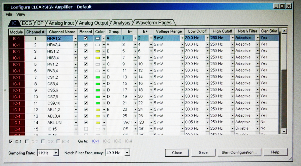
Bandwidth settings
- ECG 0.5 to 40 Hz (diagnostic ECG 0.05 to 100 Hz)
- Bipolar 30 to 500 Hz
- Unipolar - DC / 0.5 Hz - 500 Hz (HPF important)
Unipolar
- More susceptible to noise because of differential coupling of interference to the two signals
- Index of overall noise in the set up
Amplifier
Setting up signals on the amplifier
Reference for unipolar
- WCT
- Intra vascular reference
Unipolar EGM
Display set up
Setting up pages
- ECG
- Intracardiac
- Mapping / ablation
- All
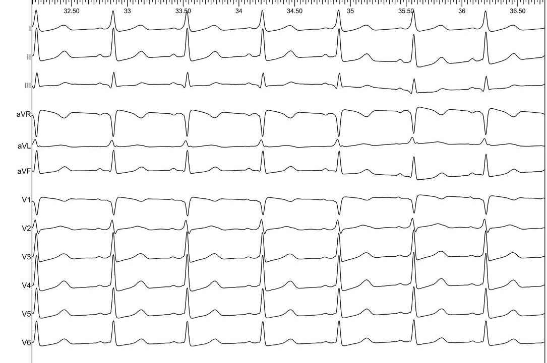
ECG page
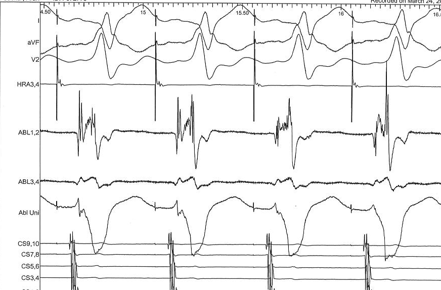
Intracardiac page
Ablation page
Setting up the signal
- Using colors
- Gain
- Clipping
Colors
Clipping - When to use
- Avoids signal overlap
- Reduces amplifier saturation obscuring information
- Masks true signal ratios, may hide small potentials
Situations where useful
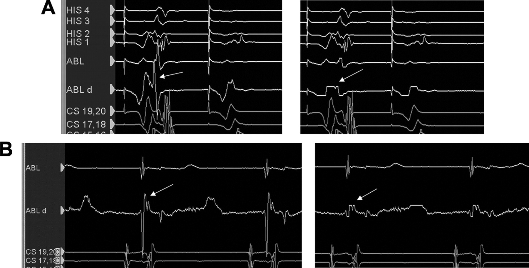
Dont clip ablation signals
Setting gain
- Equal gain for ECG leads
- Set adequate gain to see signal of interest without clipping
- For small signals (EGM within scar, His), set just above noise floor
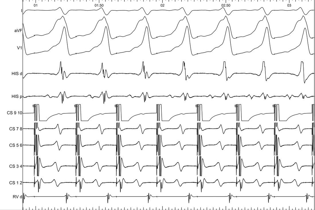
Different display modes
- Real time
- Review
- Last extrastimulus sync
- Triggered mode
- Split screen
Triggered mode
Summary
- Basics of EP lab set up
- Need to be familiar with connections, amplifier set up and display set up
- Understand the basics of signal processing
- Especially important in early career