
Setting up the EP Lab
Raja Selvaraj
Cardiac Electrophysiologist
Professor of Cardiology
JIPMER
"A journey of a thousand miles begins with a single step." — Lao Tzu
How many EP / RFA cases have you performed independently ?
- A. None
- B. Less than 50
- C. More than 50
Setup
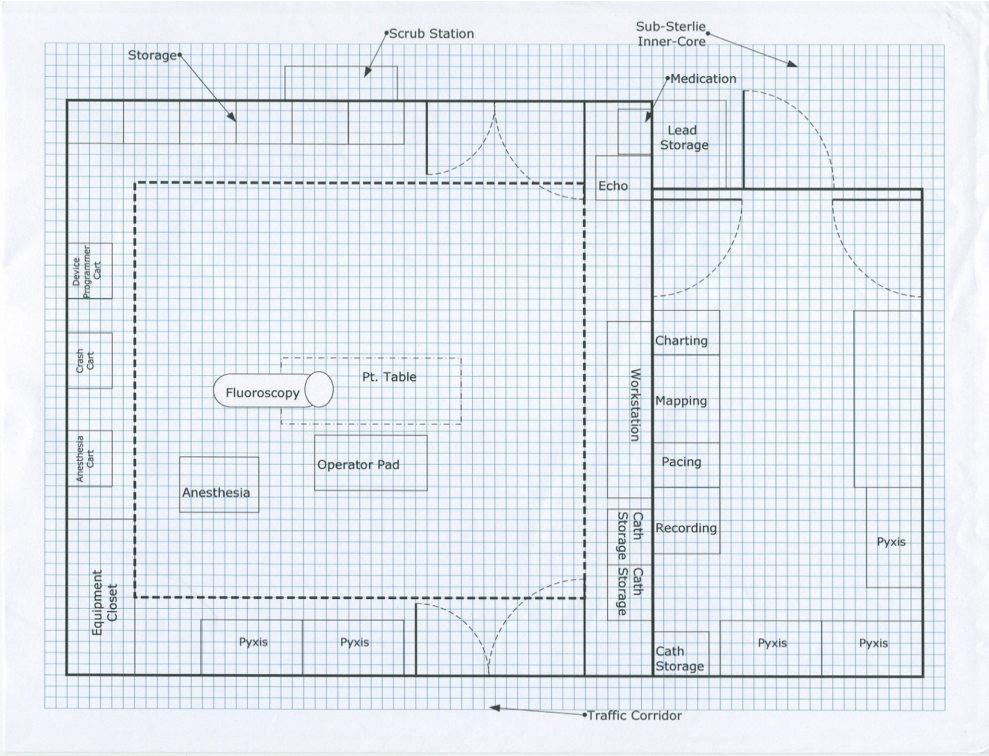
Heart Rhythm Society Expert Consensus Statement on Electrophysiology Laboratory Standards: Process, Protocols, Equipment, Personnel, and Safety 2014
Lab set up
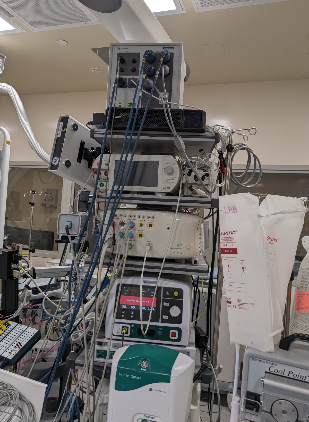
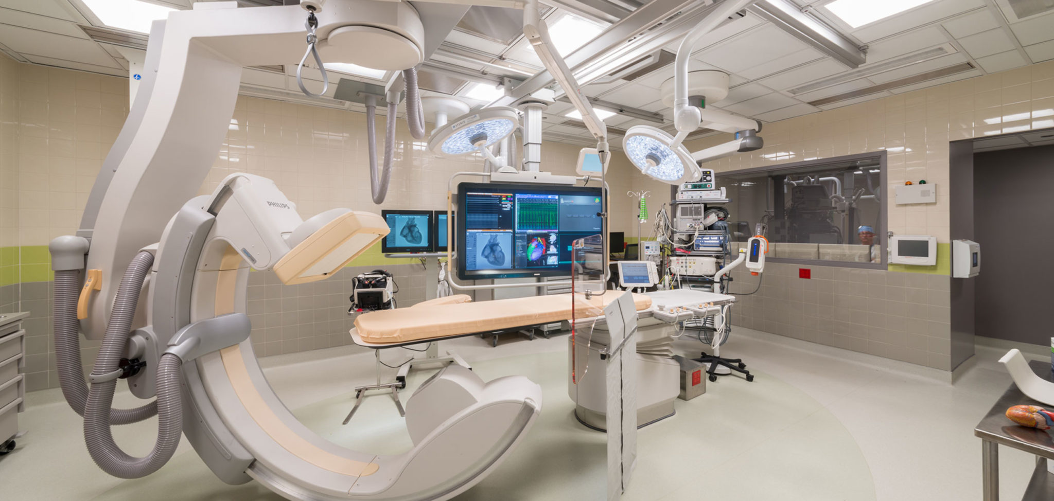
- All EP equipment on ceiling mounted equipment boom
- Power and data cables separately
- Reduce length of data cables
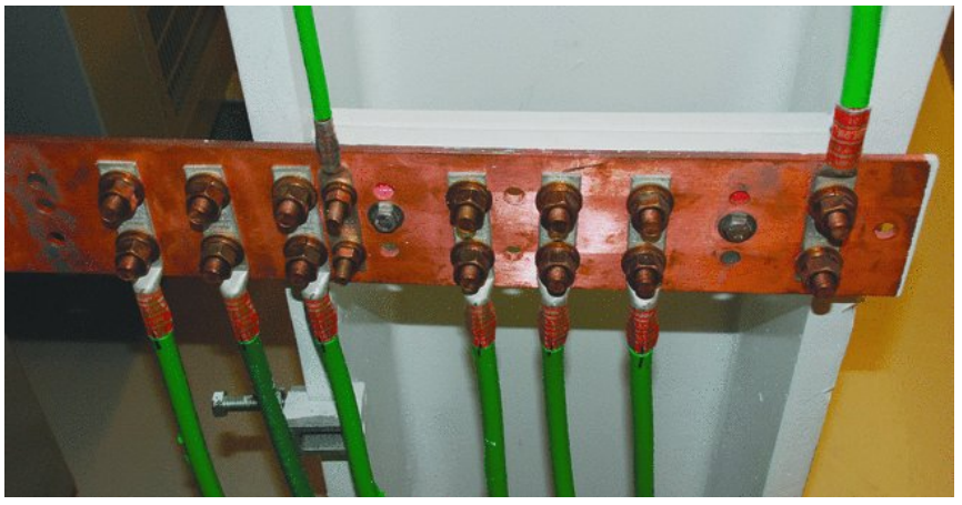
- Dedicated earth
Ceiling mounted boom
Earth
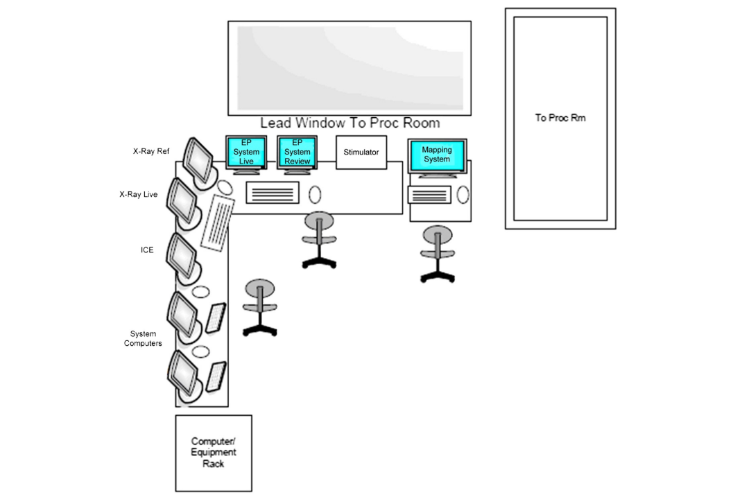
Control room
Procedure
Pre-procedure evaluation
- History
- Physical examination
- Drug history
- Anesthesia evaluation
- Echo - Ebsteins / ASD / CS
Investigations
- Adults - CBC, RFT, PT if on OAC
- Children - No consensus on required investigations
- Women of childbearing age including girls > 12 yrs - Serum or urine pregnancy testing < 2 weeks
Patients on AAD
- Usually stopped 5 half lives before
Time out
- Patient identifier
- Personnel names
- Procedure
- Allergies
Nurse administered, physician monitored intravenous sedation
- Fentanyl and Midazolam
- Continuous SPO2 and NIBP
- Avoid - Automatic AT, Idiopathic VT
I use sedation for SVT EP study
- A. Never
- B. Sometimes
- C. Always
Sedation and inducibility
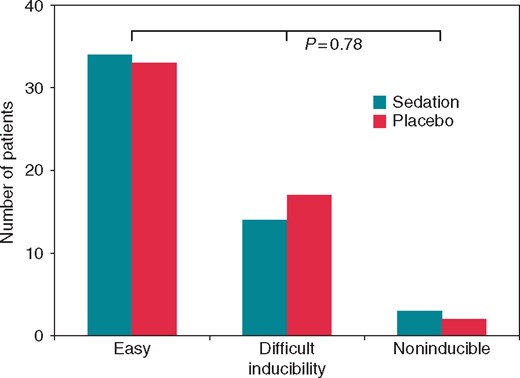
Selvaraj RJ, Dukiya S, Ananthakrishna Pillai A, Satheesh S, Balachander J. Effects of conscious sedation on tachycardia inducibility and patient comfort during ablation of supraventricular tachycardia: a double blind randomized controlled study. Europace. 2019 Jan 1;21(1):142-146. doi: 10.1093/europace/euy146.
Anticoagulation
- For all left sided procedures
- For right sided procedures
- Routinely ?
- Patent ASD
- Long sheaths
Access
Venous access
- 3 to 5
- Right femoral vein
- Left femoral vein
- Internal jugular / Axillary vein
- USG guided access
Our protocol
- 5F x 2 - RA and RV
- 6F - CS
- 7F - His / Map
Postprocedure hemostasis
- Compression if no anticoagulation
- Reversal with protamine
- Wait for ACT < 200
- Z stitch / figure of 8 suture
Imaging
Fluoro
- Digital flat panel detector
- Bi plane preferable if possible
- Integrated data display system
Radiation dose should report
- A. Fluoro time
- B. Air Kerma
- C. Dose Area Product
- D. All of the above
Reduce radiation
- Fluro loop rather than Cine loop
- Tap, not stand on fluoro
- Personal shielding
- Table shielding
What frame rate is suitable for EP studies ?
- A. 3.75 fps
- B. 7.5 fps
- C. 15 fps
- D. 30 fps
Other imaging
- Electroanatomic mapping
- TEE
- ICE
Ergonomics
- Non lead aprons (30% less weight)
- Floor or ceiling mounted radiation protection
- Comfortable table height
Catheters and connectors
Woven dacron / Polyurethane
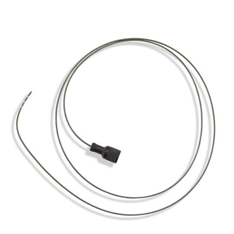
Catheters
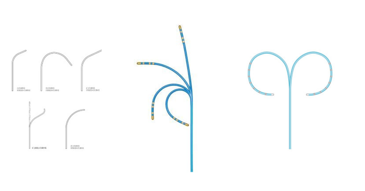
Number of electrodes

Naming of electrodes
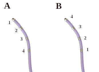
Catheter selection
- Smaller catheters more flexible, lower axial force, less stable
- Smaller spacing - more precise localization, may not pick up signal like His
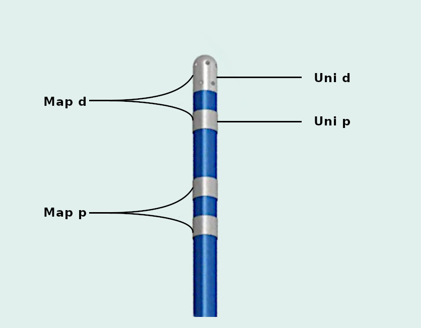
Ablation catheter
- Uni vs bidirectional
- Push-pull versus rotational handle
- Non irrigated versus irrigated
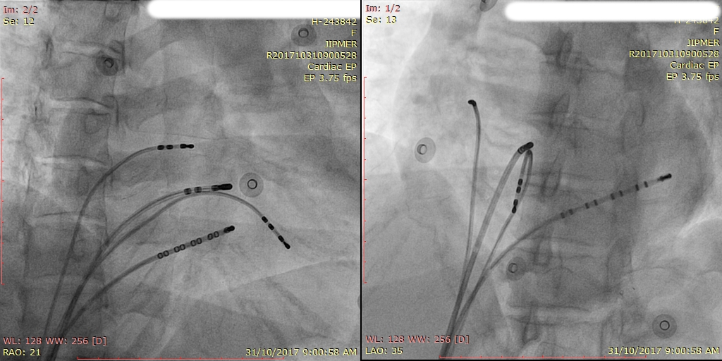
Right atrium
- Quadripolar catheter
- Right atrial appendage / lateral RA
- AP view
- Concealed RFW AP
- Atriofascicular AP
Coronary sinus
- Deflectable decapolar catheter
- Superior / inferior approach
- RAO / LAO
- Proximal electrodes at os
His
- Deflectable quadripolar catheter
- 2-5-2 spacing
- Should record atrial signal
Preferred location for RV catheter is
- A. Apex
- B. Base
- C. Midway between apex and base
RV
- Quadripolar catheter
- Basal position preferable
Catheters
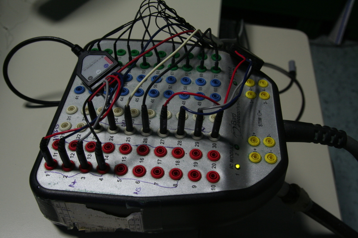
Junction box
A bird's eye view
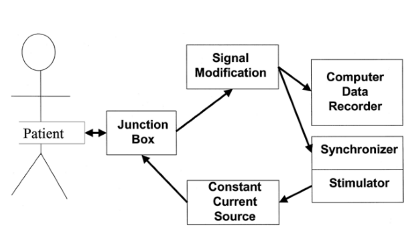
Setting up the signals
Which signal shows more noise
- A. Unipolar
- B. Bipolar
Unipolar shows more noise because
- A. Wide antenna attracts more noise
- B. Wider filter setting
- C. Differential coupling of noise to two electrodes
Bipolar vs Unipolar
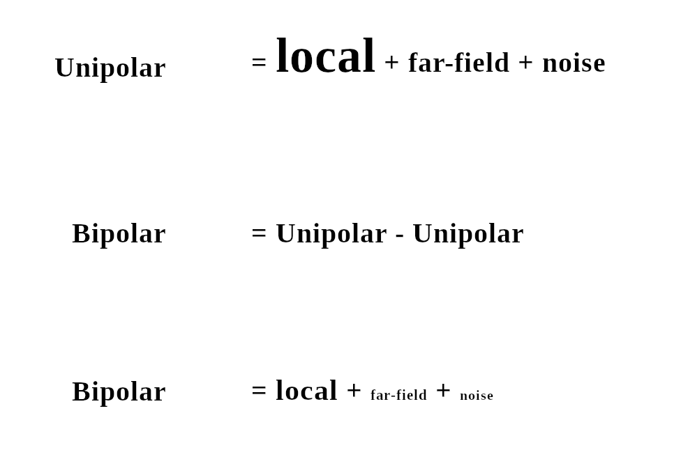
Field of view
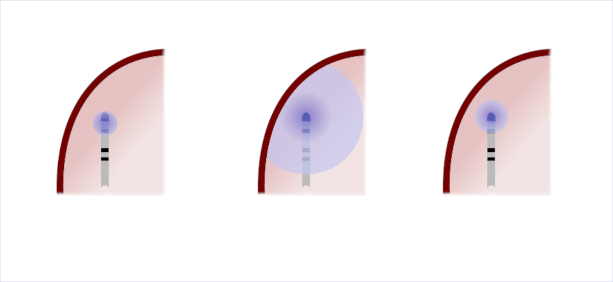
Filtered Unipolar
- Far field lower frequency signal
- High pass filter (30Hz) reduces far field component

Unipolar pacing is useful for
- A. Checking for phrenic nerve capture
- B. Entrainment in scar VT
- C. Inducing tachycardia
Amplifier set up
Steps
- Digitization
- Amplification
- Filters
- High pass
- Low pass
- Notch
Digitization

Resolution and sampling
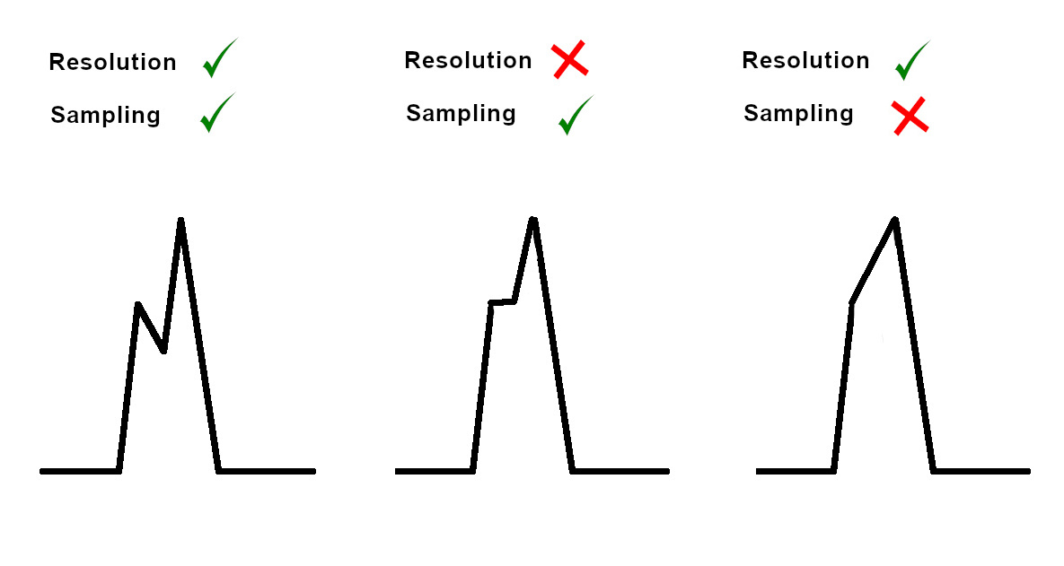
Nyquist limit
- Sampling rate should be at least twice the frequency of interest
- Lose high frequency information
- Aliasing
The challenge of intracardiac electrograms
- Very small amplitudes
- His bundle signal 0.5 mV
- Critical regions within scar may have smaller voltages - 0.25 mV
- Variation in signal amplitudes
- Surface ECG - 5 mV
Noise
Noise
- Multiple sources of noise
- Patient as antenna - picks up signals from wiring and other devices
- Leakage current from devices connected to the patient
- RF energy - 70 V RMS
- Noise level in bandwidth of interest should be 10 times smaller to give SNR > 10
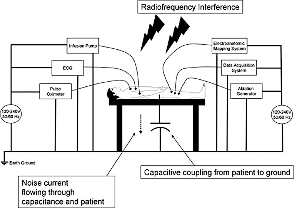
Principles to reduce noise / interference
- Decrease at source rather than reduce afterwards
- Radiation shielding also reduces electrical interference
- Separate all power cables from signal carrying cables
- When close, these should be perpendicular and not parallel
- Minimize coiling of cables
- Minimize distance between amplifier and source (patient table)
Differential amplifier
- Amplifies difference between two inputs
- Common signal is not amplified (Common mode rejection)
- Can be used to remove interference more effectively by tightly coiling two cables recording bipolar signal
- Inputs need to be balanced (ablation tip set for pacing)
Practical tips to reduce noise
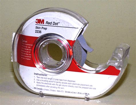
- Skin prep - dry abrasion
- Switch off unused equipment
- Try different sockets if persistent noise from an equipment
- Good grounding for all equipment
- Two return patches
- Amplifier close to patient
- Low pacing output - 2 mV, twice threshold
Skin prep
General set up
- Sampling rate 1000 Hz - 4000 Hz
- Higher sampling rate may facilitate visualization of Purkinje pot / late potentials
- More CPU work and more storage
Setting up signals on the amplifier
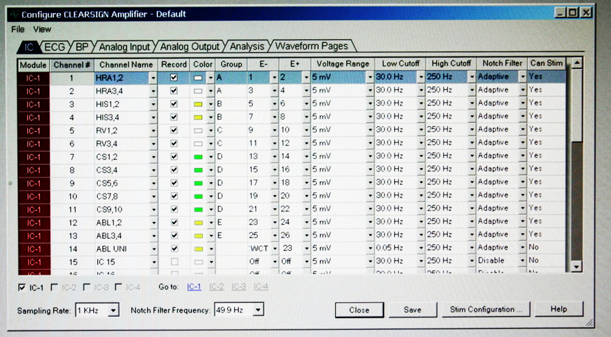
Preferred low pass filter for ECG
- 20 Hz
- 40 Hz
- 100 Hz
- 200 Hz
ECG
- 0.5 Hz
- 200 Hz
Preferred high pass filter for Bipolar EGM
- 0.5 Hz
- 5 Hz
- 30 Hz
- 100 Hz
Bipolar signals
- 30 Hz
- 300 Hz
Unipolar signals
- DC / 0.05 Hz
- 300 Hz
- Filtered unipolar signals may be useful in diseased areas
Notch filter
- 50 Hz for AC
- Avoid if possible
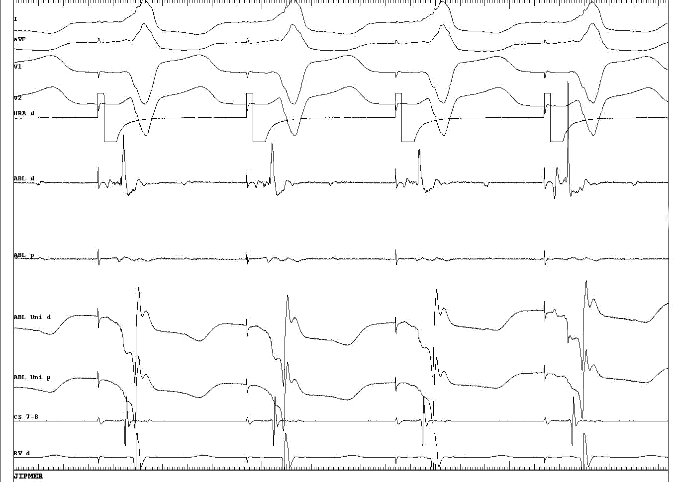
What is the issue here ?
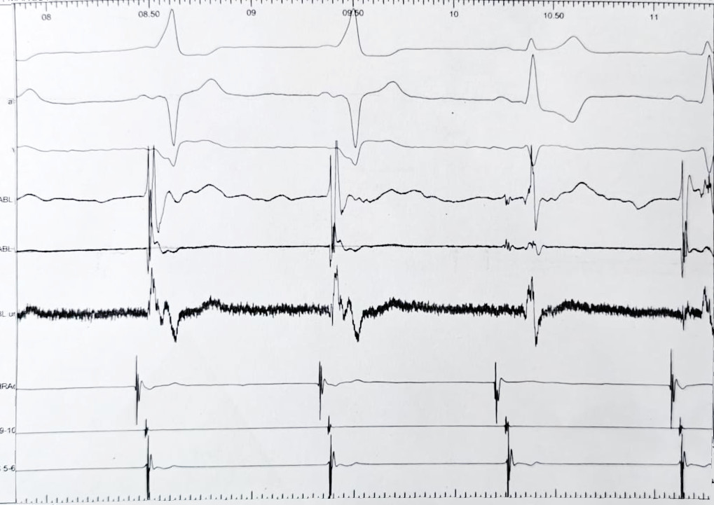
What is the source of the problem ?
- A. Noise in recording
- B. Wrong connection of unipolar EGM
- C. ECG limb lead reversal leading to inverted WCT
- D. Unipolar recorded from proximal electrode
Unipolar signal
- Exploring electrode is positive pole !

Reference for unipolar
- WCT
- Intra vascular reference
Unipolar EGM
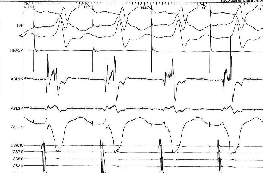
Unipolar signals for mapping
All signals are filtered at 0.05-400 in which panel ?
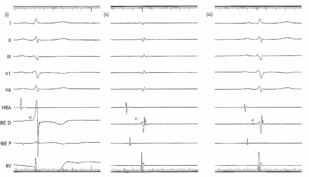
From Murgatroyd
All 0.05-400, all 30-400, correct settings

Display
Setting gain
- Equal gain for ECG leads
- Higher gains = more noise
- Very high gains = saturation of amplifier
- Set adequate gain to see signal of interest without clipping
- For small signals (EGM within scar, His), set just above noise floor
Clipping - When to use
- Avoids signal overlap
- Reduces amplifier saturation obscuring information
- Masks true signal ratios, may hide small potentials
Situations where useful
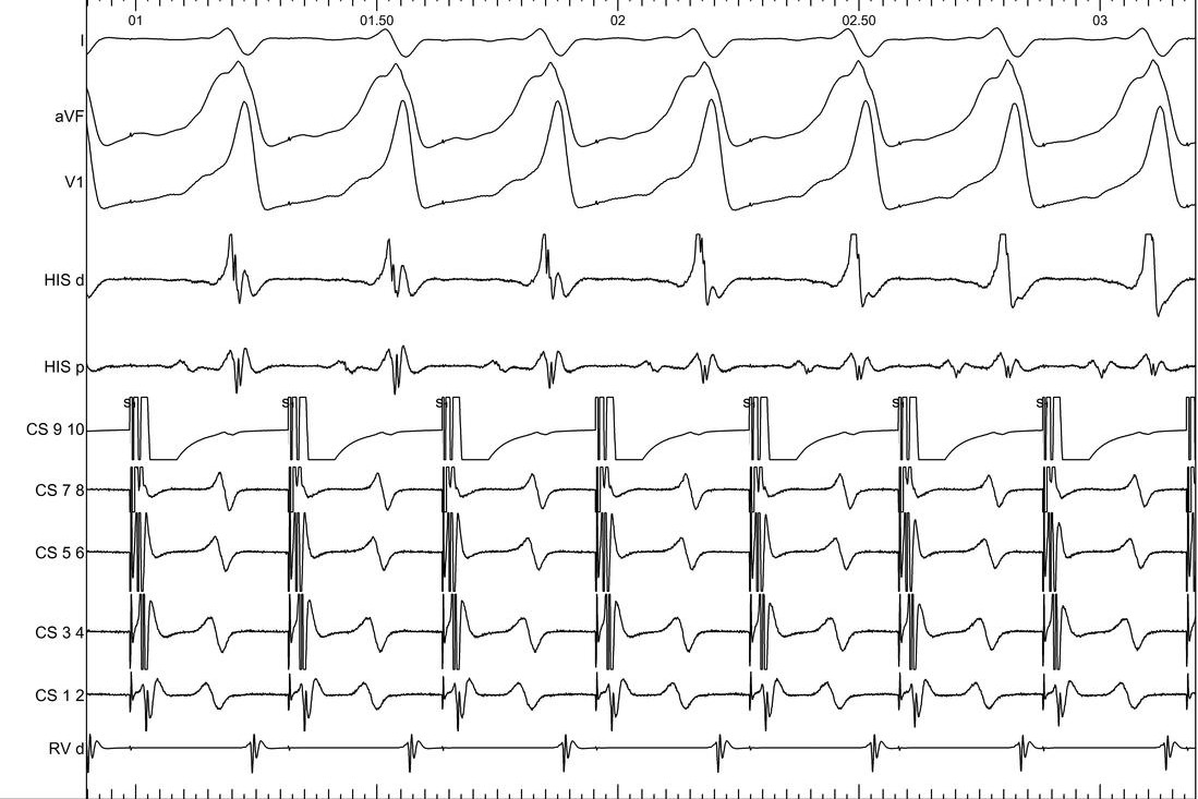
Dont clip ablation signals

Dont clip ablation signals

Pages
- ECG
- Intracardiac
- Mapping / ablation
- All
ECG page
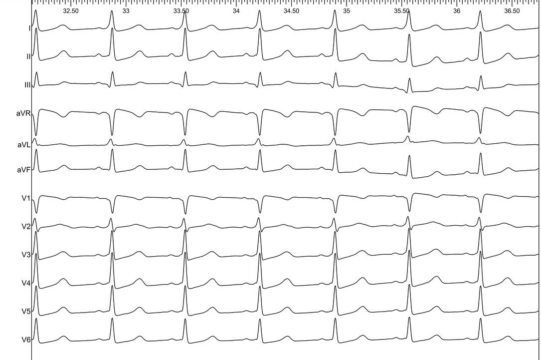
Intracardiac page
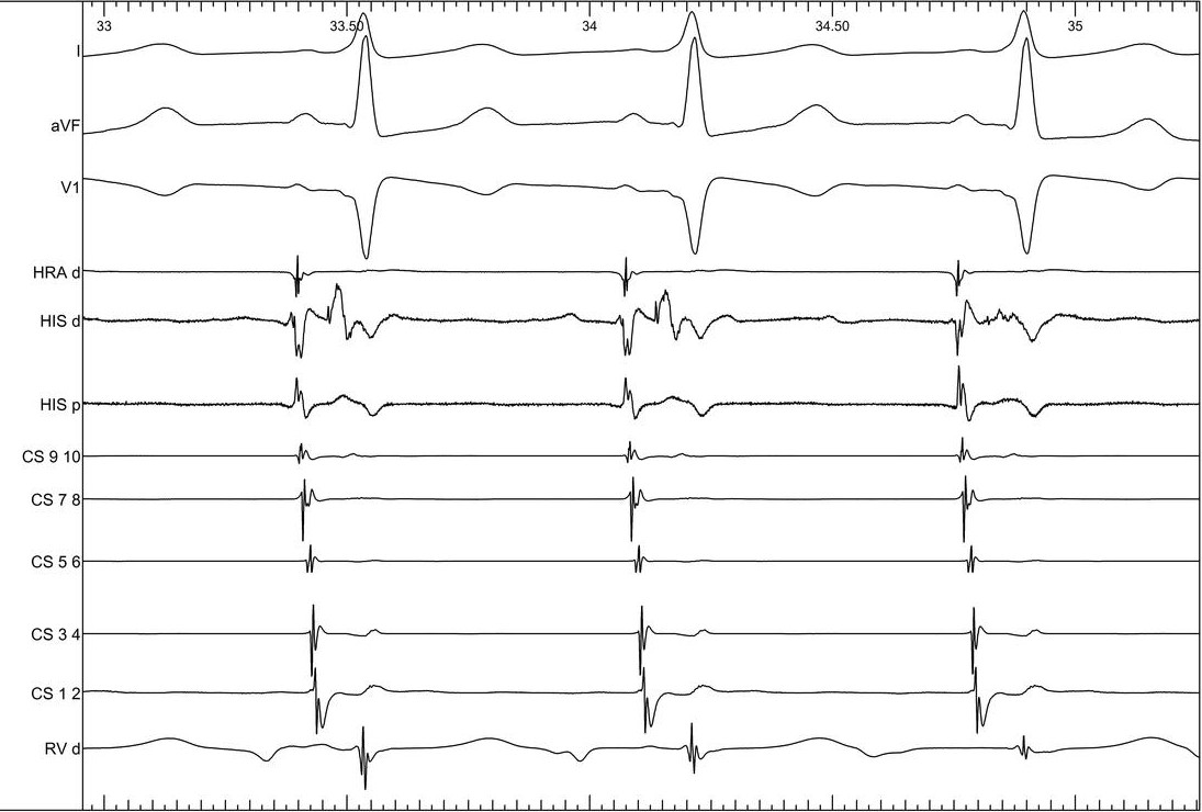
Signals and order
- 3-4 ECG signals
- HRA
- His
- CS
- RV
CS EGMs
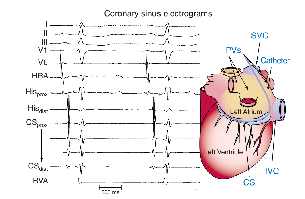
Colors
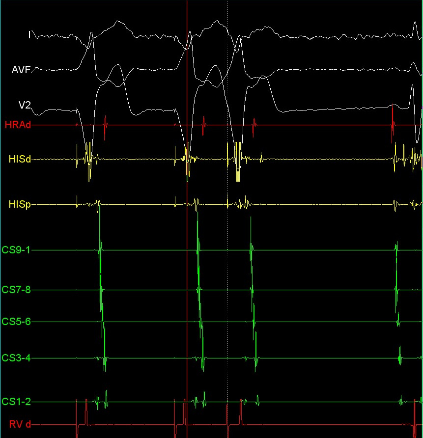
Ablation page
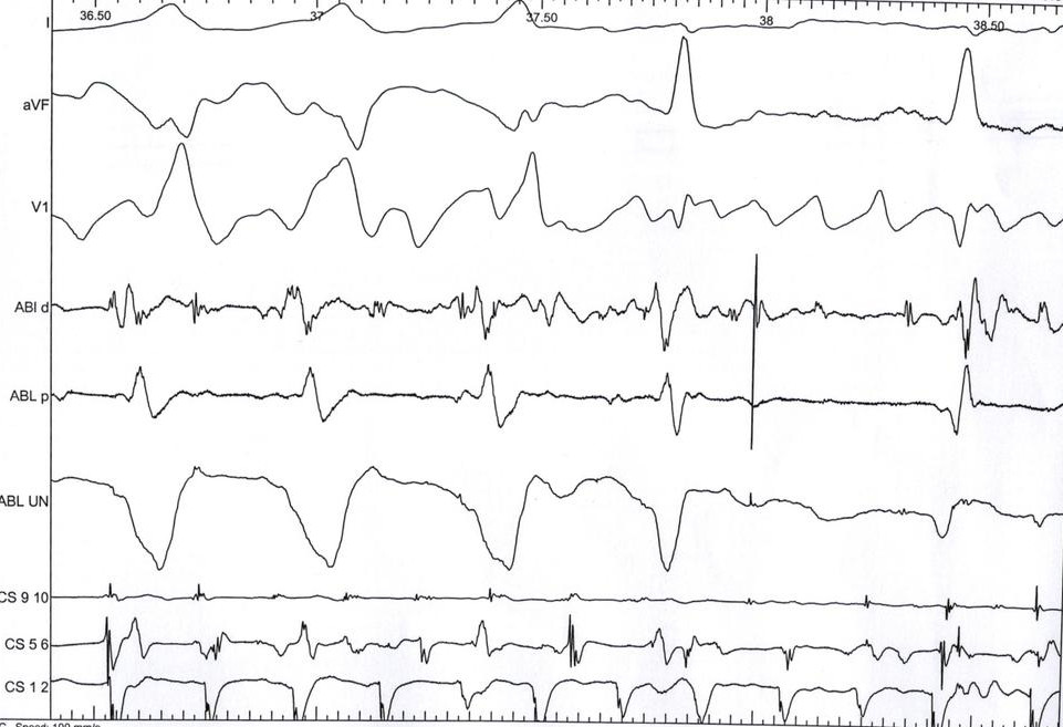
Screens / Views
Different display modes
- Real time
- Review
- Last extrastimulus sync
- Triggered mode
- Split screen
Triggered mode
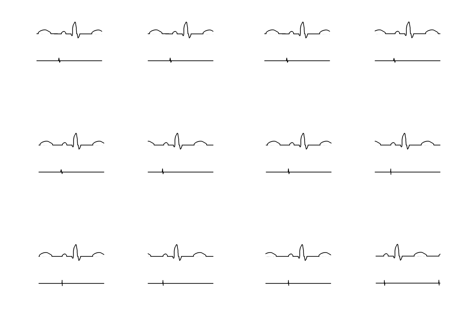
Summary - What we have discussed
- Patient evaluation and preparation before and during procedure
- Imaging, especially fluoroscopy
- Signals - setting up and use